DIY E-spinner discussion post

Recently, JoAnna mentioned that she wanted an e-spinner. I took a look and saw that they ranged in price from about a hundred bucks for the Nano espinner, to well over a thousand dollars for things like the Hansen MiniSpinner. They didn't look too complicated, so I decided to build her one. I spent a bit less than $100 parts to build a very powerful e-Spinner (not including the flyer). This is a very crude prototype device, and was assembled very quickly. Works great though, and not planning to change it until/unless something breaks!
Here are some images of it on instagram.
JoAnna happened to have a WooleeWinder for her Kromski spinning wheel that she wanted to use, so the e-spinner was designed around that. You can use pretty much any flyer that you have available, and don't have to dedicate it to the espinner, so you can switch back and forth between your regular wheel and the e-spinner. The particular flyer just will affect how you build the maidens and the platform size.
To build one of these, you or someone you know will need some basic electrical understanding, as well as maybe some simple woodworking capabilities.
Here are the main parts I'm going to discuss:
1.) bearings to support the flyer
2.) the motor
3.) drive pulley and belt
4.) the motor controller
5.) the power supply
I'm not going to focus too much on the woodworking, but mostly the motor and controller.
I will mostly say that you will need to build some maidens to support your flyer, and someplace under your flyer you will need to have room for your motor, and nearby, you'll need to have someplace to put the motor controller, and power supply and switches, etc.
BEARINGS:
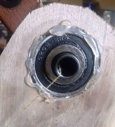
First, understand that you will need to support your flyer on maidens of some sort. JoAnna's spinning wheel supports her flyer on leather straps. That could work, but I decided to use bearings instead, to allow the flyer to spin freely. The front of Kromski Woolee-winder flyer with the orifice, nicely fits through a 13 mm sealed bearing.
I cut a hole in a piece of scrap wood (I planed it down so it wasn't much thicker than the bearing) that was to be the front maiden, and crammed the bearing into it, secured with a generous dollop of hot glue. The best adhesive since duct tape! Here's a pic:
The rear maiden has a 3/16th inch bearing in that hole supporting the woolee winder's shaft.
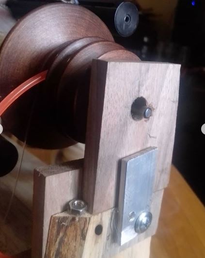
In the picture below, you'll see a few things. This is a loose piece of wood at the top of the back maiden. See the nut? I hot glued that in place as a stop. That, and the piece of aluminum hot glued/screwed onto the back keep that loose piece of wood in place. This keeps the flyer straight and level with the front maiden so it spins nice and smoothly. This piece easily twists out (bottom away from the nut, and clears the piece of retaining aluminum so that it is super quick and easy to remove the flyer or change out the bobbin. The shaft protruding through the hole is supported by a 3/16th bearing that you can't see.
MOTOR
Doing a little research, and talking to some people with e-spinners, I saw a common theme that many people think that their e-spinners are underpowered. Indeed, many use very tiny DC motors, that can't handle much power at all. It is common to overheat with heavy use. Some even have heat sinks to help dissapate the heat from overburdened motors. JoAnna likes a strong take-up when spinning, soe a stronger motor was called for. You may be able to get away with less...
I decided to use a 775 motor. a 775 motor is a brushed DC motor that is very popular. It has a LOT of torque and is used in a ton of cordless tools, like drills and reciprocating saws, etc. They're even used in hot wheels cars that your kids may be riding around in! They are also very popular in robotics kits, so if you build battlebots, you may already have one or 2 laying about. They can usually be powered from 12-36 volts. More voltage = more power. More power is not really needed in this case though. These motors have the potential to be significantly more powerful than any other espinner motor I've seen, though can still run quietly, and be well controlled for slow speeds. Note that 775 denotes a form factor for the motor, and the actual power and specs can vary from supplier to supplier. I purchased this motor from amazon.
It worked very well and came with a convenient motor mount and screws.
Very similar motors can be purchased much more cheaply, but probably without the super convenient mount that you'd then have to make yourself out of a scrap piece of angle iron or some such thing.
I also salvaged two nearly identical 775 motors from old Ryobi 18v cordless tools that also worked well, though those salvaged motors had gears permanenetly attached to their shafts that would've needed to be ground off to use them as I desired.
PULLEY AND BELT
The 775 motor has a 5 mm drive shaft. You need to add a pulley so you can drive a belt to spin your bobbin. Looking at the whorl on the flyer, I thought a 3 mm urethane belt drive seemed correct, so I looked for a pulley that would work with that. I chose this one from gobilda.com. I slides nicely over the motor's shaft and tightens down with a hex key (allen wrench).
I bought some of this belt material from amazon.com to make a drive belt. This is a 10 foot section, so if you mess up, you can practice a lot! To make the belt, you cut the correct length, and melt both ends, then stick them together very quickly. Hold until solidified, and presto - instant belt. Check youtube for a demonstration. I used a flat soldering iron tip to melt the ends of the belt. To determine the correct size, you need to know where your motor will be. The motor should be on a platform someplace, with the pulley in line with the drive whorl of your flyer. I put the motor right underneath the flyer, but ir really doesn't matter. It can be off to the side, on top, whatever crazy design you want, as long as it is mounted in a stable and strong way. Run a string around the pulley of the flyer and the motor pulley, measure it, then make a section of belt material that is 10% smaller (the belt will stretch!)
POWER SUPPLY AND MOTOR CONTROLLER
Your motor needs a power supply and speed controller. You can just use a 12V battery for the power supply, and hook it up to a 12v charger when not in use. OR, you can buy a plug in power supply. the 775 motor is fairly powerful, and should probably have a 12 volt, 10 amp power supply. I have seen some reports that a 5 amp power supply will work with 775 motors, and other reports that a 5 amp supply will NOT work with 775 motors. I know that THIS ONE from amazon will work just fine. This power supply has a DC barrel connector attached.
DC barrel connectors are the standard 5.5 mm plug that you've probably used a million times. They are mostly used for low power applications, like charging, and 10 amps is a bit on the high side for them. You could do a couple things, like cut off the barrel connector and put Anderson connectors on the end, or try to find a DC port that is rated for 10 amps. I did find some of those, again on AMAZON, and they worked OK. These DC ports come with 2.1 mm or 2.5 mm center pins. Make sure you get the size that matches your power supply, or it won't fit right.
I cut a small hole in the rear maiden and inserted the power socket, to which I soldered lengths of 16 gauge flexible wire. Red for +, black for - (all you can see in this picture though is black heat shrink). With this power supply, the (+) is the center post. I made sure to put good heat shrink over the terminals on the jack, because arcing is a thing that could happen here.

Those wires are then connected to the...
MOTOR CONTROLLER
I'm told that the e-spinner needs to spin in both directions. So, I bought a reversible DC motor controller. I used this one, again from AMAZON. It is probably way overkill for this application, but works great. It has an on/off direction switch, and a speed control dial. For this, all you have to do is connect the positive and negative wires from your new power outlet, and then put wires from the positive and negative output for the motor leading to tabs on the motor. I put connectors like these that crimp on to the wires to connect to the tabs on the motor. The other side of the wire just screws onto the block on the coltroller.
In this pic, you can see the motor controller. The wires from the power supply are connected on the right, and the wires to the motor are on the left. You can see the motor on the right.

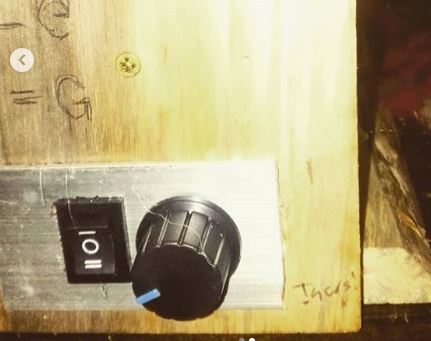
The power supply has a switch and a speed dial. I made a panel for them out of a piece of scrap aluminum. Drilled a couple holes and cut out the shape for the switches using a dremel with a rotary cutting bit. Used the same dremel to cut an appropriate sized hole in the front maiden, and hot glued the entire panel in like this:
We're almost done now! Assuming you've built an appropriate set of maidens and platform, and everything is mounted in a good way, make sure you leave a room for your scotch tension device. I found a spring in my spring kit that worked perfectly. (You do have a spring kit, don't you?)
Drilled 2 small holes for eyelets in the platform beneath the flyer, attached the spring to one (first feedback, that eyelet with the spring should be a hook instead, so the scotch tension can be removed more easily for bobbin changes). Tied on 50lb monofilament fishing line, up over the bobbin, and through the eyelet on the other side...

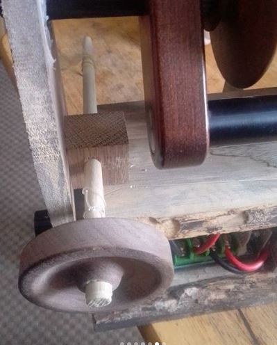
And the down towards the front maiden, where it is attached to the tensioning knob. In this case, I used a half finished drop spindle that I didn't care for. I drilled a tiny hole in the shaft, and threaded the monofilament through it, and tied it off. The spindle is mounted in a block that's glued to the platform, with a hole tht is bigger than the thinner end, but smaller than the thicker end. You don't need a spindle, and piece of dowel with something glued to the end would work just fine. Just drill the hole a little smaller than the dowel, and then sand it down until it fits.
Well - I think that is pretty much it. Here is a video of it in action.
Total cost of parts that I had to purchase to build this:
Motor: $18.39
Power Supply: $18.98
Motor Controller: $18.89
Bearings (bought 10 packs, only needed one of each): $18.42
Pulley: $3.99
Drive belt (10 ft, way too much): $6.39
DC power connectors (pack of 3): $5.99
Everything else was scrap wood, or already laying around the workshop (hot glue, dremel, eyelets, screws, aluminum bits, etc.
So - total cost to build, just under 100 bucks for an espinner that works really well. It has tons of power to drive the woolee winder with the strong take-up that JoAnna really likes. The motor is quiet, and I can detect no heat from the motor or controller, even after heavy use. I suspect this motor is way overkill, but will do any job asked of it. If you went for a less powerful DC motor, you can save quite a bit of money. Limiting the motor, power supply and motor controller to 3 amps or less really would probably cut more than half the cost out of the project with cheaper controllers, etc. Indeed, there are many espinners out there that do use motors even less powerful than that, and they make many people very happy (Nano spinner, etc.)
Have fun and happy building! Feel free to post any questions in the comments, I'll try to answer them if I can!
-Bill
You can definitely work a foot pedal into the design. A quick search for DC reversible motor controller with foot pedal brings up a few options. These are pretty beefy, and maybe way overkill for an espinner, but should work OK. IF you have someone with electronics knowledge, you could probably just buy a stand alone foot pedal switch and replace the speed control switch on any other motor controllers with the pedal.
I know this post is several years old but curious if you can hook up a sewing machine pedal to this somehow? I know how to do everything else based on reading this and watching some videos but I only saw one with a pedal and that was using a sewing machine motor that the woman said was quite loud so I was looking for an alternate motor with the same capabilities. Thanks!!
Hmm. That motor controller looks to be a DPDT relay to control polarity for forward and reverse, a potentiometer wired 2 ways to control speed and a 3 way rocker switch to activate the DPDT relay. Whats got me puzzled is those tiny heat sinks, like its got a few mosfets or transistors. Like its about to read hall sensors, run a 3 phase motor and Pulse width modulate like a real motor controller.
Thank you for the detailed instructions and, most importantly, links to the various components! The links to sources for the metal pulley wheel and drive band material are particularly helpful. I’m going to try this with my Lendrum wheel’s flyer/maiden assembly and the corresponding Woolee Winder that I have.
Thank you for sharing these detailed instructions and sourcing links. I am an avid DIYer and excited to build my own electric spinner! I’ll let you know how it goes.